How to Choose a Temperature and Pressure Relief Valve?

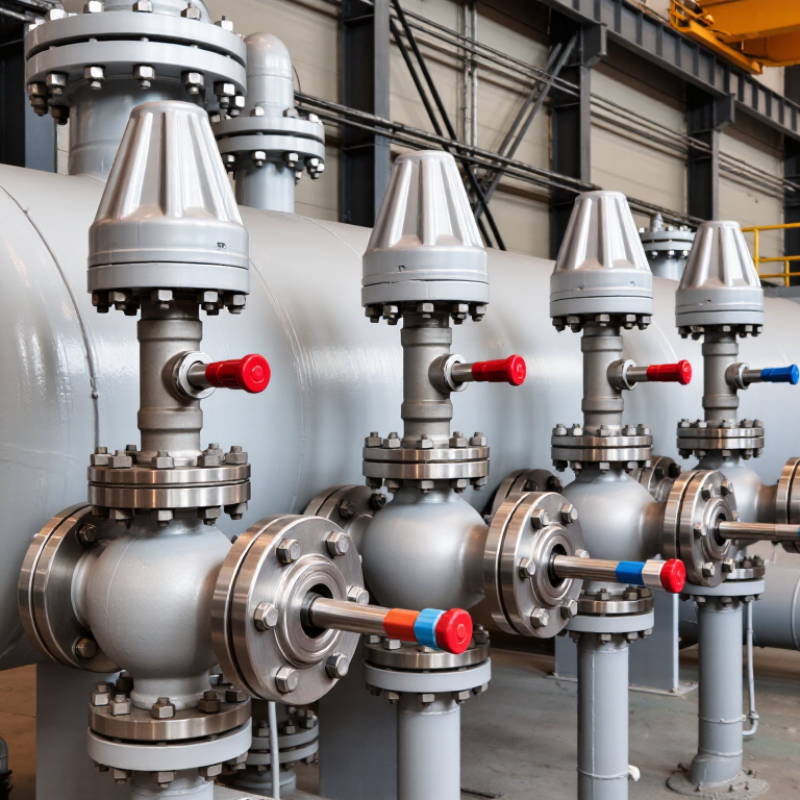
Choosing a temperature and pressure relief valve is a safety decision, not a catalog exercise. The correct device must protect equipment from excessive pressure, overheating, or both. A small stainless-steel valve may look suitable beside a boiler, reactor, or storage vessel. Its real performance depends on set pressure, temperature range, discharge capacity, fluid properties, and installation conditions.

Industry standards provide the technical foundation. ASME Boiler and Pressure Vessel Code Section VIII addresses overpressure protection for pressure vessels. ASME Section XIII also establishes requirements for pressure-relief devices. API Standard 520 Part I covers sizing and selection, while API 521 discusses relieving systems and disposal arrangements. ISO 4126-1 provides requirements for safety valves. In the United States, OSHA 29 CFR 1910.169 requires pressure vessels to have suitable protective devices. These references do not replace engineering judgment. They support it.

Field experience reveals the uncomfortable part. A valve can pass a bench test and still perform poorly in service. Corrosion may weaken the spring. Dirt can hold the disc slightly open. A blocked discharge pipe can turn a correct calculation into a dangerous installation. National Board incident records and investigation reports repeatedly highlight maintenance, installation, and inspection failures. Therefore, selection should begin with verified process data, not a familiar brand. Confirm the vessel’s allowable working pressure, operating temperature, relieving scenario, backpressure, and required flow rate. Then compare materials, connection sizes, certification, inspection access, and testing intervals. The choice is rarely perfect. It should be documented, reviewed, and reconsidered when the process changes.

How to Choose a Temperature and Pressure Relief Valve?

Understanding the Purpose of a Temperature and Pressure Relief Valve

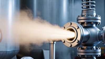
A temperature and pressure relief valve protects a sealed heating system from dangerous pressure or heat buildup. It opens when either condition exceeds its rated limit. The valve then releases hot water or steam through a safe discharge pipe. This action can prevent tank damage, pipe failure, and serious injuries.

Its purpose becomes clearer near a storage water heater. Imagine water expanding inside a full tank while heating. Pressure rises quietly. If a control fails and the temperature keeps climbing, the valve provides a final mechanical safeguard. It does not regulate everyday pressure. It responds during abnormal conditions. That distinction matters when choosing the correct valve.

Selection should match the equipment’s pressure rating, temperature range, connection size, and heating capacity. The discharge line should terminate safely, remain visible, and avoid caps or unnecessary restrictions. Local plumbing codes usually define these details, so a qualified professional should verify the installation. In field checks, a valve may look clean but still fail to operate properly. Testing procedures must follow the manufacturer’s instructions and applicable regulations. Replacement is often wiser when corrosion, leakage, or mineral buildup appears. No choice is perfect. Even experienced installers can overlook a mismatched rating or an obstructed outlet. A careful inspection makes the valve’s protective purpose real, not merely documented.

Identifying System Temperature, Pressure, and Fluid Requirements

How to Choose a Temperature and Pressure Relief Valve?

Identifying system temperature, pressure, and fluid requirements is the practical starting point. Record the normal operating pressure, maximum working pressure, and possible pressure spikes. A valve set too close to normal pressure may open repeatedly. That wastes fluid and can damage the seat. Measure temperature during startup, steady operation, cleaning, and shutdown. Thermal expansion can create pressure even when the pump is off. Do not rely on one gauge reading. I prefer checking instrument accuracy and reviewing maintenance records before selecting a valve.

Fluid behavior also matters. Water, steam, oil, air, and corrosive chemicals require different materials and discharge calculations. Note the fluid phase, viscosity, density, toxicity, and tendency to crystallize. A small amount of trapped liquid can freeze or expand sharply. The valve must release enough flow to protect the vessel under the worst credible condition. Confirm inlet and outlet sizes, back pressure, connection type, and temperature limits from current technical documents. A common mistake is choosing by pipe size alone.

Tips: Write down real operating data, not assumptions. Check pressure in the coldest and hottest locations. Ask whether the fluid may change phase. Verify set pressure, capacity, material compatibility, and discharge routing with a qualified engineer. Test and document the valve after installation. I still recheck calculations when field conditions differ from the original design. Small details often decide whether protection works.

How to Choose a Temperature and Pressure Relief Valve? - Identifying System Temperature, Pressure, and Fluid Requirements

Selection Dimension What to Identify Realistic Example or Reference Value Effect on Valve Selection Verification Needed
Protected Equipment Vessel, boiler, water heater, heat exchanger, piping section, or other pressure-containing equipment. A closed hot-water storage vessel with a maximum allowable working pressure of 10 bar(g). The valve must protect the component with the lowest allowable pressure rating. Review equipment nameplates, drawings, calculations, and applicable local regulations.
Normal Operating Pressure The pressure normally maintained during steady operation. 6 bar(g) at the vessel inlet. The set pressure should be above normal operating pressure to prevent nuisance lifting while maintaining adequate protection. Confirm pressure readings at cold start, normal load, and maximum operating load.
Maximum Allowable Working Pressure The highest pressure the protected equipment is designed to withstand at a specified temperature. 10 bar(g) at 120 °C. The relief-valve set pressure must not exceed the permitted limit of the protected equipment, subject to the governing code. Check the pressure-temperature rating of the vessel, connections, flanges, and piping.
Valve Set Pressure The pressure at which the relief valve is adjusted to open under the specified test conditions. 8 bar(g) for equipment with a 10 bar(g) allowable limit, where permitted by the applicable code. The setting must balance operating stability with protection against overpressure. Confirm the required set pressure from the design calculation and jurisdictional requirements.
Overpressure and Blowdown Allowable pressure rise above set pressure and the pressure reduction required before reseating. A liquid-service valve may be specified with a small reseating differential, while code limits vary by application. The valve must have certified capacity and blowdown characteristics suitable for the selected service. Use the governing pressure-vessel or piping code and the valve certification data.
Normal Operating Temperature The fluid temperature during normal operation. 90 °C for a pressurized hot-water system. The valve materials, spring range, seals, and temperature rating must be compatible with continuous service. Measure or calculate the highest stable operating temperature, not only the average value.
Maximum and Minimum Temperature Temperature during start-up, shutdown, upset conditions, heat soak, cold ambient exposure, and depressurization. Operating range from 5 °C to 120 °C. Temperature extremes can affect material strength, seal performance, viscosity, and the pressure rating of the valve. Compare the full temperature range with the valve body, trim, spring, gasket, and seat ratings.
Fluid Phase Whether the relief medium is liquid, vapor, gas, steam, or a flashing two-phase mixture. Compressed air: gas service; saturated water above its boiling condition: flashing or steam-related service. Sizing equations and valve construction differ substantially between liquid and gas or vapor service. Determine the phase at the valve inlet and during discharge, including possible flashing.
Fluid Composition Chemical composition, concentration, additives, contaminants, dissolved gases, and solids. Water containing 30% glycol by volume, or dry compressed air with a small amount of oil aerosol. Composition affects corrosion resistance, elastomer compatibility, viscosity, density, and discharge capacity. Use the current fluid safety data and chemical compatibility information for all wetted materials.
Fluid Properties for Sizing Density, molecular mass, specific gravity, viscosity, compressibility, vapor pressure, and heat capacity. Water density is approximately 998 kg/m³ at 20 °C; air density varies significantly with pressure and temperature. Accurate properties are required to calculate required relief capacity and select the effective discharge area. Obtain properties at relieving temperature and pressure rather than at room conditions.
Required Relief Load The maximum mass or volumetric flow that must be discharged during the credible overpressure scenario. A blocked-outlet liquid expansion case may require 2,000 kg/h of relief capacity. The selected valve must pass at least the calculated required flow under relieving conditions. Evaluate fire exposure, thermal expansion, control-valve failure, utility failure, and blocked discharge scenarios where applicable.
Inlet Pressure Loss Pressure drop between the protected equipment and the relief-valve inlet. A long, narrow inlet pipe with several elbows can create excessive pressure loss during discharge. Excessive inlet loss can cause instability, chattering, or reduced effective capacity. Calculate inlet losses at the required relief flow and keep the inlet arrangement as direct as practical.
Discharge Back Pressure Pressure at the valve outlet caused by downstream piping, a header, a scrubber, or atmospheric restrictions. A closed discharge header operating at 1.5 bar(g) above atmospheric pressure. Built-up and superimposed back pressure can alter set pressure, capacity, and valve stability. Determine whether the back pressure is constant, variable, built-up, or superimposed.
Material Compatibility Compatibility of the body, spring, disc, seat, seals, gaskets, and connection materials with the fluid and environment. Water-glycol service may require seals and internal materials rated for glycol concentration and operating temperature. Incorrect materials can cause corrosion, swelling, embrittlement, leakage, or premature failure. Check chemical compatibility, corrosion allowance, cleanliness requirements, and environmental exposure.
Connection Size and Type Inlet and outlet nominal size, thread or flange type, pressure class, and face-to-face dimensions. A DN25 inlet with a DN40 outlet, using a flanged connection suitable for the system pressure class. Connections must provide adequate flow area, mechanical strength, and installation compatibility. Match the valve connections with the piping specification and verify allowable loads on the equipment nozzle.
Relief Valve Type Spring-loaded, pilot-operated, temperature-and-pressure combination, or another approved relief arrangement. A temperature-and-pressure relief valve for a domestic hot-water storage vessel; a spring-loaded safety valve for compressed air. The valve type must match the hazard, fluid phase, pressure range, temperature range, and required response. Confirm that the selected type is permitted for the application by the governing code and authority.
Temperature Relief Function Required temperature activation point where excessive heating could create unsafe pressure or scalding risk. A storage-water application may use a temperature limit near 99 °C, but the exact value depends on the applicable standard and design. The temperature element must be located where it senses the actual protected fluid temperature. Verify the required temperature setting, tolerances, sensor immersion, and discharge arrangement.
Discharge Routing Where discharged fluid, vapor, or gas will go and whether the route is safe and visible. A drain line routed downward to a safe termination point, with no isolation valve between the vessel and relief valve. The discharge system must prevent personnel exposure, backflow, blockage, freezing, and unacceptable back pressure. Review drainage, venting, support, slope, termination, insulation, and local installation rules.
Code and Certification Applicable pressure equipment, boiler, piping, plumbing, or safety-valve requirements. Pressure-vessel relief devices may require capacity certification under the applicable national or international code. A technically suitable valve may still be unacceptable if it lacks the required certification or approval. Identify the installation jurisdiction and confirm required markings, test certificates, and inspection intervals.
Maintenance and Testing Inspection frequency, manual test requirements, replacement parts, calibration, and access for service. A valve in continuous industrial service may require periodic inspection based on risk, code, fluid condition, and operating history. A valve that cannot be safely inspected or maintained may not provide dependable long-term protection. Create a documented inspection and testing plan without disabling the only overpressure protection.
Important: Set pressure, relief capacity, temperature setting, materials, and installation details must be confirmed by a qualified engineer using the applicable local code and the protected equipment design data.

Selecting the Correct Valve Type, Size, and Pressure Rating

How to Choose a Temperature and Pressure Relief Valve?
Selecting the correct valve starts with the equipment’s maximum allowable working pressure, not normal operating pressure. The valve’s set pressure must protect the weakest component in the system. It should also open reliably at the specified temperature. Check the fluid carefully. Steam, hot water, thermal oil, and corrosive liquids require different valve designs and materials. Small details matter, including discharge direction and connection type.
Valve size depends on required relief capacity, not simply pipe diameter. Calculate the possible heat input, flow rate, pressure increase, and relieving conditions. A valve that matches the pipe may still be undersized. Review inlet pressure loss and outlet backpressure, because both can reduce performance. For a closed discharge system, confirm that the outlet can handle the released fluid safely. Keep the route short and avoid unnecessary bends.
Pressure rating must cover the highest operating temperature, since material strength can decrease as temperature rises. Select compatible seals and body materials after checking the fluid chemistry. Certification and test documentation should come from a qualified manufacturer or inspection provider. In practical inspections, blocked outlets, incorrect set points, and poor maintenance appear repeatedly. They are easy to overlook. I would also recheck the sizing calculation after changing a heater, pump, or operating fluid. That step can feel excessive, but system modifications often change the relief requirement. A final review by a competent engineer adds useful independence.

Checking Materials, Standards, Installation, and Maintenance Needs

How to Choose a Temperature and Pressure Relief Valve?

Material selection should match the fluid, temperature range, pressure, and surrounding environment. Stainless steel may resist corrosion, but it is not automatically suitable for every chemical. Check body, spring, seal, and connection materials separately. A hot-water system may need seals rated for continuous heat, not brief exposure. Review the manufacturer’s compatibility data and pressure-temperature charts carefully. Small assumptions can cause expensive failures.

Confirm that the valve meets the standards required in its installation location. These may cover design, testing, sizing, discharge capacity, and inspection. The set pressure must stay below the protected equipment’s allowable working pressure. Ask for traceable test records and certification from a competent testing organization. A familiar-looking valve is not proof of compliance. Local requirements can differ, too.

Installation affects performance as much as selection. Mount the valve in the correct orientation, with a short, unobstructed inlet. Keep discharge piping supported and directed toward a safe drain point. Never isolate the valve with an unapproved shutoff device. During maintenance, inspect for corrosion, leakage, blocked outlets, and damaged seals. Test according to the equipment manual and applicable rules. Record each result, including the test date and set pressure. One practical weakness remains: maintenance schedules often look precise, yet real operating conditions may demand earlier inspection.

Verifying Valve Performance Before Final Selection

How to Choose a Temperature and Pressure Relief Valve?

Verifying Valve Performance Before Final Selection

When selecting a temperature and pressure relief valve, published specifications are only the starting point. The final decision should reflect actual operating conditions, not estimated values. I have learned this through inspections where a small pressure difference changed the valve’s response. Start with the set pressure, operating temperature, fluid state, required capacity, and discharge arrangement. Record each value beside its source.

Before approval, request performance evidence from a controlled test bench. Verify set pressure at the specified temperature whenever possible. Measure blowdown, reseating pressure, leakage, and opening capacity. Check whether the valve reaches stable lift without chatter or sudden oscillation. These details reveal behavior that a catalog table cannot show. Do not accept a generic test statement without traceable results.

Review the calibration record, test date, instrument accuracy, and technician authorization. Confirm that materials suit the fluid and temperature range. Inspect the inlet and outlet connections for restrictions, because poor installation can distort test results. A certificate is useful, but it is not a substitute for technical review. Small errors matter. I still recheck calculations after witnessing a satisfactory test, especially when back pressure is variable. Ask for evidence under conditions close to the real system. If the available test differs significantly, document the limitation before final selection.