North American Safety Valve Industries, Inc.North American Safety Valve Industries, Inc.North American Safety Valve Industries, Inc.
In 2026, the temperature and pressure relief valve market is moving from basic protection toward smarter, application-specific safety. Grand View Research identifies process automation, energy infrastructure, and industrial expansion as important market drivers. MarketsandMarkets also reports growing demand for safety valves across oil and gas, power generation, chemical processing, and water treatment. The numbers look encouraging, but market forecasts are not field evidence. A valve still faces heat, corrosion, vibration, and poor maintenance.
This guide examines spring-loaded, pilot-operated, thermal, combination, and electronic relief valve designs. It compares response speed, set pressure, temperature range, materials, certification, and maintenance access. In a boiler room, a small pressure rise can lift a valve seat within seconds. In a chemical line, the wrong alloy can fail quietly. That detail matters.
Valve specialist Les Driskell wrote, “A relief valve is a safety device, not a process-control device.” That distinction remains essential. The valve should protect equipment during abnormal conditions, not replace sound operating procedures. API 520, API 521, ASME Section VIII, and the National Board’s inspection guidance provide recognized technical foundations. However, standards alone cannot guarantee performance. Sizing errors, blocked discharge paths, incorrect installation, and neglected testing still occur. This article therefore considers both established engineering practice and its uncomfortable gaps. The best choice is not always the most advanced valve. It is the valve correctly sized, correctly installed, and verifiably maintained for the actual service.
What Are Temperature and Pressure Relief Valves?
Temperature and pressure relief valves protect closed systems from dangerous heat and pressure. A valve opens when either condition exceeds a preset limit. It then releases steam, hot water, or process fluid through a safe discharge path. The mechanism is simple. The responsibility is not.
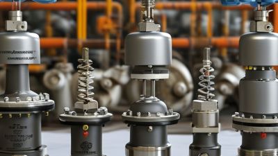
Pressure-only relief valves respond to excessive pressure. Spring-loaded designs suit many boilers, pipelines, and pressure vessels. Pilot-operated valves can provide more accurate control in large, high-pressure systems. Temperature and pressure relief valves combine a spring mechanism with a thermal element. They are common in hot-water storage equipment. The thermal element reacts to abnormal water temperature, while the spring responds to pressure.
The U.S. Energy Information Administration reported that water heating represented about 19% of residential energy use in 2020. That energy creates real scalding and overpressure risks. ASME Boiler and Pressure Vessel Code Section VIII addresses pressure-relief protection for many industrial vessels. Product certification and correct sizing still require competent engineering review. A valve with the wrong set pressure may open too late. A poorly routed discharge pipe may injure people. Small details matter.
Field inspections often reveal blocked outlets, corrosion, or missing test records. These failures are preventable, but maintenance schedules are sometimes treated as paperwork. That is a weakness worth admitting. Operators should verify set pressure, temperature rating, flow capacity, installation direction, and discharge routing against the equipment design and applicable local requirements.
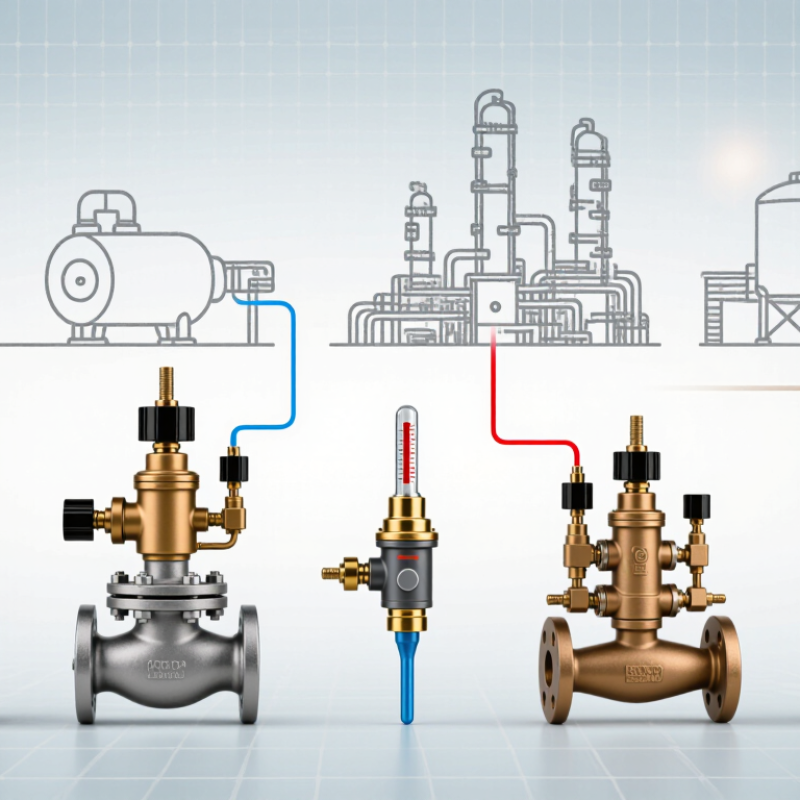
Temperature and pressure relief valves are safety devices designed to release excess pressure, excessive temperature, or both to help protect pressure equipment, piping, water heaters, boilers, storage vessels, and process systems.
| Valve Type | Primary Protection | How It Operates | Typical Set-Point or Rating Range | Common Applications | Key Advantages | Main Selection Considerations |
|---|---|---|---|---|---|---|
| Pressure Relief Valve (PRV) | Excess pressure in liquid or gas systems | Opens automatically when system pressure reaches the calibrated set pressure and closes after pressure is reduced. | Commonly selected from approximately 1 to 400 bar, depending on equipment design and applicable code. | Pressure vessels, pumps, pipelines, hydraulic systems, and general industrial equipment | Simple, reliable, and available for a wide range of pressures and fluids | Set pressure, relieving capacity, fluid compatibility, back pressure, discharge routing, and applicable safety code |
| Safety Valve | Excess pressure in compressible fluids such as steam, air, and gas | Usually opens rapidly with a lifting action to discharge enough fluid to prevent dangerous overpressure. | Often used in steam and gas systems from low pressure to high-pressure service. | Boilers, steam lines, compressed-air receivers, gas systems, and process equipment | Fast opening response and high discharge capability for compressible media | Steam or gas capacity, blowdown, inlet pressure loss, discharge piping, operating temperature, and noise control |
| Temperature and Pressure Relief Valve (T&P Valve) | Excess water temperature and pressure | A temperature-sensing element opens the valve when water becomes excessively hot; a pressure-sensing mechanism opens when pressure exceeds the set point. | A common domestic water-heater configuration is approximately 99°C temperature and 10.3 bar pressure, but the correct rating depends on the equipment specification. | Storage water heaters, hot-water tanks, and thermal fluid vessels | Protects against two independent hazards in one valve | Temperature rating, pressure rating, probe length, discharge pipe size, installation orientation, and local plumbing requirements |
| Pressure Safety Valve (PSV) | Overpressure in process and energy systems | Uses a spring, pilot, or other actuator to open at a predetermined pressure and provide certified pressure protection. | Available across broad pressure and temperature ranges; the set pressure must remain below the protected equipment's allowable working pressure. | Refineries, chemical plants, power facilities, storage vessels, and process piping | Suitable for engineered safety systems requiring documented performance | Required relieving rate, certified capacity, inlet and outlet pressure losses, built-up back pressure, materials, and inspection requirements |
| Pilot-Operated Pressure Relief Valve | High-pressure or high-capacity overpressure events | A small pilot valve controls the main valve, allowing system pressure to help keep the main valve closed until the set condition is reached. | Common in medium- and high-pressure services where large flow capacity or close pressure control is required. | Large gas pipelines, production systems, high-pressure vessels, and process plants | Stable operation near set pressure and high capacity with comparatively compact main-valve sizing | Pilot reliability, clean instrument fluid, minimum operating pressure, back pressure, response time, and maintenance capability |
| Spring-Loaded Relief Valve | General pressure protection | A calibrated spring holds the disc closed until system pressure overcomes the spring force. | Commonly used from low pressure to high pressure, with the spring selected for the required set pressure and temperature. | Steam, air, gas, liquid, boilers, vessels, and industrial utility systems | Compact construction, direct actuation, and comparatively straightforward maintenance | Spring temperature effects, set-pressure accuracy, fluid phase, capacity, vibration, back pressure, and material selection |
| Thermal Relief Valve | Pressure caused by trapped liquid thermal expansion | Opens at a relatively small pressure increase to relieve liquid expansion in blocked-in piping or equipment. | Typically uses a low relief capacity and a set pressure selected above normal operating pressure but below the allowable system limit. | Blocked-in liquid lines, heat exchangers, pump discharge sections, and liquid-filled piping | Protects small isolated liquid volumes from temperature-related pressure rise | Liquid expansion volume, trapped-section temperature, discharge destination, corrosion resistance, and pressure differential |
| Vacuum Relief Valve | Excessive negative pressure or vacuum | Opens inward when internal pressure falls below the valve's vacuum set point, allowing air or inert gas to enter the system. | Often selected for low differential pressures, commonly measured in millibar, kPa, or inches of water column. | Storage tanks, low-pressure vessels, tank farms, and systems subject to draining or condensation | Helps prevent tank collapse, deformation, and damage caused by vacuum conditions | Vacuum set point, required airflow, tank design pressure, gas compatibility, flame-arresting needs, and environmental conditions |
| Combination Pressure-Vacuum Relief Valve | Both overpressure and vacuum conditions | Uses separate pressure and vacuum functions in one assembly to release excess pressure or admit air when internal pressure becomes too low. | Usually applied to atmospheric or low-pressure storage systems with independently specified pressure and vacuum settings. | Fuel and chemical storage tanks, water tanks, food-processing vessels, and bulk liquid storage | Provides bidirectional protection while reducing the number of tank connections | Pressure and vacuum capacity, vapor emissions, tank breathing rate, fluid properties, temperature, and cleaning requirements |
| Sanitary Pressure Relief Valve | Overpressure in hygienic process systems | Relieves pressure through a smooth, cleanable internal design, often using a spring-loaded mechanism. | Set pressure and temperature vary by process equipment; hygienic systems commonly require low-crevice construction and validated materials. | Food, beverage, dairy, pharmaceutical, and biotechnology processing | Cleanability, corrosion resistance, and reduced risk of product contamination | Surface finish, elastomer compatibility, clean-in-place requirements, dead-leg control, sanitary connections, and validation documentation |
| Burst Disc with Relief Valve System | Rapid emergency pressure relief | A non-reclosing rupture disc bursts at a defined pressure; it may be installed alone or combined with a reclosable relief valve. | Disc burst pressure is specified at a stated temperature and manufacturing tolerance; it is not normally field-adjustable. | Reactive processes, corrosive services, pressure vessels, and systems requiring leak-tight isolation | Very fast response, tight sealing before activation, and compatibility with certain corrosive or viscous services | Burst tolerance, operating-to-burst-pressure ratio, temperature, fragment control, replacement requirements, and interaction with any relief valve |
| Electronic or Smart Relief System | Monitored pressure and temperature events | Electronic sensors and control logic detect abnormal conditions and activate an electrically or pneumatically actuated relief device. | Set points are configured according to the protected equipment and control-system design; sensor accuracy and response time are critical. | Automated plants, energy systems, remote installations, and safety-instrumented applications | Remote monitoring, event recording, diagnostics, and integration with plant control systems | Fail-safe behavior, power-loss response, cybersecurity, sensor redundancy, proof testing, environmental rating, and independent mechanical backup |
Selection note: The correct relief valve must be sized using the maximum credible relieving scenario, required relieving capacity, set pressure, allowable working pressure, operating temperature, fluid phase, material compatibility, installation conditions, and the applicable local code or standard. Set points and temperature ratings must always be verified against the equipment manufacturer's specifications.