Sizing a pressure relief valve is not a matter of matching the valve inlet to the pipe. It is a safety calculation based on the system’s credible overpressure scenarios, required relieving capacity, fluid properties, and permitted pressure limits. A valve that looks right on a specification sheet can still be unsuitable when backpressure, temperature, or installation details change.
As pressure-relief engineering guidance puts it: “Size for the governing relief case, then verify the complete installation.” This is a practical summary, not a quotation attributed to a named expert. Without a supplied source, assigning those words to an individual would be misleading. Reliable sizing should instead be checked against the applicable design standards, manufacturer data, and qualified engineering review.
The outline that follows explains how to define the relief scenario, calculate required capacity, select a valve type, and check inlet and discharge piping. It also covers common mistakes, such as overlooking built-up backpressure or assuming normal operating flow determines valve size. Small details matter. A long discharge line, a changing fluid phase, or a sticky service can alter performance.
Real systems are rarely tidy. Sometimes the available process data are incomplete, and that uncertainty deserves attention rather than a neat guess. The goal is a pressure relief valve that can protect the equipment under the defined conditions—and can be inspected, maintained, and verified in its actual installation.
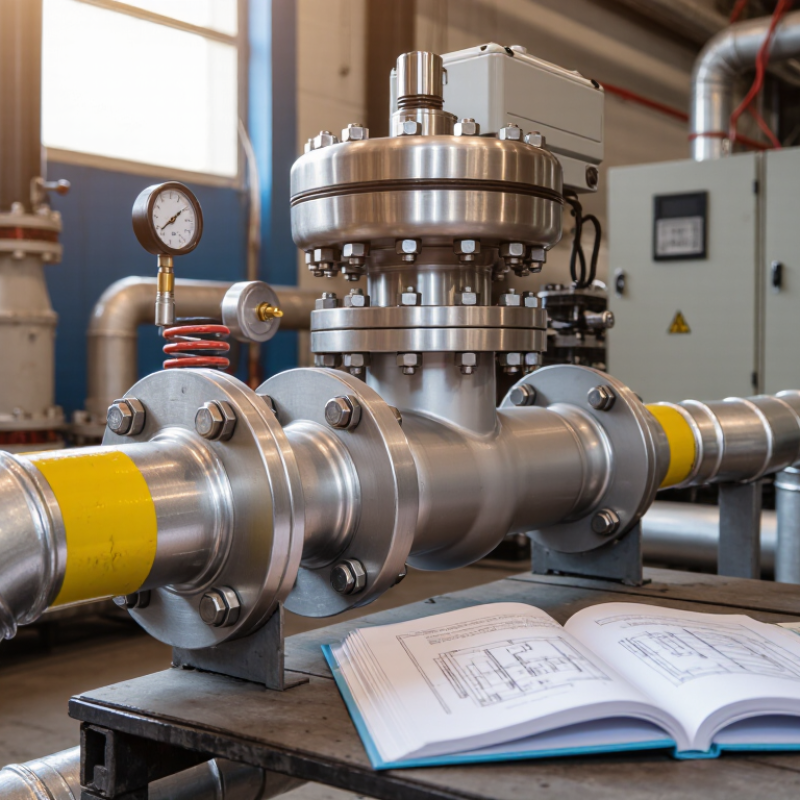
Sizing begins with scenario definition, not valve diameter. List every credible overpressure source for the protected vessel or line. Recognized guidance, including API 521, identifies blocked outlet, fire exposure, thermal expansion, tube rupture, and control failure as core cases. Describe the initiating event in one sentence. Then state the fluid, phase, temperature, pressure, composition, and response time. A vague case creates a precise-looking mistake.
For blocked outlet, calculate the maximum upstream flow at the relieving pressure. For external fire, estimate heat input from the wetted surface and insulation condition. Thermal expansion can be severe. A small liquid pocket may create a large pressure rise. Record whether discharge enters a collection system or vents locally. The protection target is not always preventing rupture. It may involve toxic exposure, vessel collapse, or escalation. The UK Health and Safety Executive reported 138 worker fatalities in Great Britain during 2023/24. That figure is not a relief-valve statistic, but it keeps consequence analysis grounded. People stand near equipment.
Use design pressure, accumulation limits, backpressure, and required relieving capacity from the governing code. Check simultaneous scenarios only when process design makes them credible. Do not simply add every load. The first scenario list is rarely complete. Review operating logs, alarm histories, maintenance records, and utility failures with operations personnel. Then challenge the assumptions: Is the fire size realistic? Can an isolation valve close accidentally? Will viscosity change at low temperature? A documented scenario basis supports defensible selection of the valve, inlet line, discharge piping, and inspection interval.
A relief valve is sized for the governing credible scenario. The chart compares representative required relieving-flow capacities for common overpressure cases in a process vessel. Final sizing requires validated process data, fluid properties, code calculations, and manufacturer-certified capacity coefficients.
Basis: representative vessel design pressure of 10 barg, valve set pressure of 10 barg, and relieving pressure of 11 barg including a typical 10% accumulation allowance. Required capacity values are expressed as mass flow and are intended to illustrate scenario comparison rather than replace a project-specific calculation.
Before sizing a pressure relief valve, collect verified process data for the equipment it protects. Record the fluid composition, phase, operating pressure, temperature, and expected flow. Include vapor or liquid properties needed for calculation, such as molecular weight, density, and heat capacity. Small omissions matter. A changing mixture can alter the required valve capacity.
Establish the design conditions for each credible overpressure scenario, such as blocked discharge, external fire, or control failure. Document the set pressure, permitted overpressure, relieving temperature, and any built-up or superimposed backpressure. Check inlet piping losses and discharge-system limits, too. Use current process documents, then confirm key values with operations staff. A spreadsheet may look tidy while its assumptions remain wrong. Have a qualified engineer review the governing case against the applicable design requirements.
Tips: Keep units consistent, label every data source, and flag estimated values. If operating conditions have changed, revisit the basis before selecting a valve.
Choosing a pressure relief valve starts with the service, not the catalog. A spring-loaded valve may suit conventional vapor or liquid duties. A pilot-operated design can help when normal operating pressure is close to set pressure, though contamination or pilot-line issues may affect performance. A rupture disk offers non-reclosing protection and may be installed with a relief valve when the design requires it. Small details matter.
Then identify the applicable sizing standard and governing code. For many process applications, engineers use API 520 for valve sizing and selection, alongside API 521 when evaluating relief scenarios. Pressure vessels may also fall under ASME Section VIII requirements. The governing jurisdiction and equipment rules determine which requirements apply; confirm the current editions rather than relying on a familiar reference alone. Standards are not interchangeable.
Sizing depends on the credible overpressure case, required relieving capacity, fluid properties, temperature, set pressure, and permitted accumulation. Backpressure can also change the choice of valve and its capacity. A gas calculation needs different inputs from a liquid calculation, so check units and property data carefully. In practice, the first calculation is rarely the final one. Compare the selected valve’s certified capacity with the required load, and document assumptions for review. Real operating data can be imperfect, so flag uncertain inputs instead of hiding them.
| Service or condition | Typical device type | Applicable standards and their role | Key sizing and selection data | Important checks |
|---|---|---|---|---|
| Gas or vapor; backpressure is low and reasonably stable | Conventional spring-loaded pressure relief valve | API 520 Part I provides sizing methods; the applicable ASME code establishes vessel requirements and capacity certification rules. | Required relieving rate, set pressure, allowable overpressure, relieving temperature, molecular weight, compressibility and heat-capacity ratio, plus inlet and outlet conditions. | Superimposed and built-up backpressure can affect performance. Check inlet pressure loss, allowable accumulation and certified capacity. |
| Gas, vapor or liquid service with variable or significant superimposed backpressure | Balanced bellows spring-loaded valve | API 520 Part I for sizing; applicable ASME code for installation and certified-device requirements. | Required relieving rate, set and relieving pressures, temperature, fluid properties, and expected superimposed and built-up backpressure. | A bellows can reduce the effect of backpressure on set pressure and capacity, but does not remove all backpressure limits. Verify bellows pressure, temperature and material limits. |
| Service requiring consideration of backpressure or operation near normal operating pressure | Pilot-operated pressure relief valve | API 520 Part I provides sizing guidance; applicable ASME code and device certification requirements still govern. | Required relieving rate, set and relieving conditions, fluid properties, backpressure, pilot configuration and the manufacturer’s certified capacity data. | Confirm suitability for the fluid, temperature, contamination or plugging risk, backpressure range and minimum operating differential. Follow certified device limits. |
| Steam service on a boiler or pressure vessel | Code-certified safety valve appropriate to the equipment | ASME BPVC Section I applies to power-boiler safety valves; Section VIII applies to pressure vessels. Use the governing code’s capacity and certification rules. | Required steam capacity, set pressure, allowable overpressure, relieving pressure and temperature, and code-required certified capacity. | The governing equipment code and jurisdiction determine the requirements. Do not substitute a general sizing calculation for required code certification. |
| Liquid service, including blocked-in liquid thermal expansion | Spring-loaded relief valve selected for liquid service | API 520 Part I includes liquid sizing methods; API 521 helps identify and evaluate relief scenarios and disposal-system considerations. | Required liquid relieving rate, density at relieving conditions, viscosity where relevant, vapor pressure, relieving pressure, backpressure and temperature. | Use the correct scenario basis: thermal expansion flow can differ substantially from process relief flow. Check flashing, cavitation, inlet losses and discharge-system effects. |
| Two-phase or multiphase flow | Device selected for the specific two-phase application | API 520 Part I and API 521 provide relevant sizing and scenario guidance; ISO 4126-10 addresses sizing of safety devices for gas/liquid two-phase flow. | Relieving rate and pressure, temperature, phase fractions, fluid properties, flow regime and the basis used to predict two-phase flow. | Do not apply single-phase gas or liquid equations without confirming their applicability. Use an appropriate validated method and document its assumptions. |
Note: API 521 is principally used to identify and evaluate overpressure scenarios and relief-system design; it is not a substitute for the applicable valve sizing method. Confirm the adopted standard editions, equipment code, jurisdictional rules, certified valve data, and consistent units before final selection.
How to Size a Pressure Relief Valve?
Calculate Required Relief Capacity and Valve Orifice Area
Start by identifying the credible overpressure scenario: a blocked outlet, external fire, or liquid trapped between closed valves. Each case can require a different relief rate. Calculate the maximum inflow or heat-driven vapor generation the valve must handle, using the fluid’s properties at relieving conditions. Then establish set pressure, permitted overpressure, and built-up backpressure. Small details matter. A normal operating flow is not a substitute for required relief capacity.
For a preliminary liquid estimate, use A = Q / [Cd × √(2ΔP/ρ)], with consistent units. Here, Q is required flow, Cd is the discharge coefficient, ΔP is pressure drop across the valve, and ρ is fluid density. This simplified relationship assumes incompressible flow; viscosity, piping losses, and backpressure can change the result. Gas and steam require compressible-flow equations that account for temperature, molecular weight, and possible critical flow.
Compare the calculated area with the valve’s certified effective orifice area, then verify rated capacity under the actual installation conditions. Don’t round down. An early estimate may look neat yet miss a changed fluid composition or a restrictive inlet line. Check the applicable sizing standard and have a qualified engineer review the scenario, inputs, and final selection before specifying the valve.
Sizing a pressure relief valve starts with credible process data, not a catalog chart. Define the governing overpressure case, relieving rate, set pressure, temperature, fluid phase, and allowable back pressure. API 520 Part I identifies these inputs as central to capacity selection. For gases and vapors, calculate compressibility and molecular weight carefully. For liquids, include viscosity and flashing risk. A spreadsheet can look precise and still be wrong.
Selection must be verified against installation conditions. ASME BPVC Section VIII, Division 1, paragraphs UG-125 through UG-136, addresses overpressure protection for applicable vessels. API 521 provides guidance for fire exposure, blocked outlets, and thermal expansion scenarios. Check inlet pressure loss, discharge reaction forces, drainage, isolation valves, and safe vent routing. Keep the inlet line short where practical. Small mistakes matter.
Operating performance needs evidence. Compare the certified capacity with the calculated relieving load, then confirm set pressure, blowdown, leakage limits, and back-pressure correction. ISO 4126-1 provides requirements for safety valves and their performance testing. API 576 recommends inspection practices, including seat condition, spring integrity, and corrosion checks. Test records should show actual settings, test medium, temperature, and calibration status. Field conditions can differ from design assumptions. That deserves another review.