Choosing an air compressor relief valve is a pressure-safety decision, not a simple purchasing task. The correct valve must match the compressor’s maximum allowable working pressure, discharge capacity, connection size, temperature, and air quality. A valve that looks suitable may still release too slowly during a rapid pressure rise.
Maintenance expert R. Keith Mobley often emphasizes, “Reliability is designed into equipment; it is not inspected into it.” That principle fits compressed-air systems closely. A relief valve should be selected from verified pressure data, then installed where trapped air can reach it without restriction. For example, imagine a receiver tank beside a compressor room wall. Its gauge reads 8 bar, the valve is rated for 10 bar, and the discharge outlet points toward a walkway. The numbers seem acceptable, but the installation still needs careful review.
This guide explains how to choose an air compressor relief valve with practical engineering checks. It covers set pressure, flow capacity, materials, certification, thread compatibility, and maintenance access. It also considers moisture, oil carryover, vibration, and temperature changes. These details are easy to overlook.
One warning deserves attention. A relief valve is not a pressure regulator, and it cannot correct a failed control switch. It is a final protective device. That distinction is sometimes blurred in real workshops. I have seen specifications copied from older equipment without confirming the receiver’s current rating. That shortcut can create uncertainty.
Use the compressor manual, receiver nameplate, manufacturer data, and applicable safety standards together. When those sources disagree, stop and obtain qualified engineering advice. Expect careful verification, not guesswork.
An air compressor relief valve protects the receiver from dangerous overpressure. It releases air when pressure exceeds a preset limit. Pressure changes fast. A correctly selected valve protects equipment, workers, and production schedules.
The first reference point is the receiver’s maximum allowable working pressure, or MAWP. OSHA 29 CFR 1910.169 states that receiver safety valves must prevent pressure from exceeding this limit. The valve should never be isolated by a shutoff valve. ASME Boiler and Pressure Vessel Code Section VIII also supports documented pressure-relief design and testing. These requirements turn valve selection into an engineering task, not a quick purchase.
Check the valve’s set pressure, discharge capacity, connection size, temperature range, and air compatibility. ISO 4126-1 provides requirements for safety valves used against excessive pressure. The U.S. Department of Energy reports that compressed air can represent about 10% of industrial electricity use, although the share varies by facility. That makes leaks and unnecessary pressure especially costly. A valve with poor capacity may not relieve pressure quickly enough. A valve with an unsuitable setting may open repeatedly. Small details matter.
Inspect the valve for corrosion, blocked discharge paths, and damaged seals. A clean exterior proves little. I would also compare the current operating pressure with real pressure logs, rather than relying on memory. That step is easy to skip, and sometimes it exposes an imperfect installation. Use qualified personnel for testing, and keep calibration records tied to the compressor and receiver.
Choosing an air compressor relief valve starts with pressure, not valve size. Record the compressor’s maximum allowable working pressure, receiver rating, and normal operating range. The valve’s set pressure must remain below the weakest rated component. ISO 4126-1 treats safety valves as protective devices, not routine pressure controls. That distinction matters. A valve that opens too often may indicate poor system control or an incorrect setting.
Temperature also changes the decision. Hot discharge air can weaken seals and alter spring performance. Check the manufacturer’s temperature range, then compare it with measured outlet temperatures during peak demand.
The U.S. Department of Energy reports that compressed air can consume 10–15% of electricity in manufacturing facilities. Small pressure losses can therefore create measurable operating costs.
I have seen teams select a valve from pipe diameter alone. That shortcut is risky. Flow capacity, back pressure, air quality, and installation position deserve equal attention.
Tips:
Photograph the nameplate before ordering. Measure pressure at the receiver and near the compressor. Confirm whether oil mist, moisture, or outdoor exposure affects materials. Ask for certified capacity data at your actual pressure and temperature. Recheck the set pressure during commissioning.
A rushed inspection can miss a blocked discharge path, and that weakness may remain invisible until the system is stressed. DOE compressed-air guidance also recommends minimizing unnecessary pressure and leakage, so valve selection should support the entire system, not just one vessel.
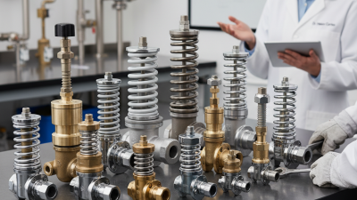
Choosing an air compressor relief valve starts with the failure it must prevent. For small reciprocating compressors, a spring-loaded valve is often practical and responsive. It opens directly when pressure exceeds the calibrated setting. Pilot-operated valves suit larger, steadier systems with higher flow demands. They can control pressure accurately, but they need clean pilot air and careful maintenance. That detail is easy to overlook. A valve should never be selected by pressure rating alone.
Material choice affects service life. Brass works well in clean, dry air and moderate temperatures. Stainless steel offers stronger corrosion resistance in humid or chemically exposed rooms. Carbon steel may handle demanding industrial service, but its surface protection requires inspection. Check the seat and seal material, too. Elastomers must tolerate the compressor’s temperature, oil carryover, and cleaning methods. A material can look robust and still fail early. I would verify compatibility from technical data, not appearance.
Connection options also influence installation reliability. Threaded NPT or BSP connections fit compact equipment, but mismatched threads can damage the body or leak. Flanged valves provide stronger alignment for larger pipework and easier removal during testing. Compression connections suit smaller lines when vibration is limited. Leave enough clearance for inspection and discharge piping. The set pressure must match the compressor’s permitted working pressure and the system’s verified design data. Use documented test results and current applicable standards. A final leak check matters. Even a correctly sized valve becomes unreliable when installed crookedly, blocked, or discharged into an unsafe location.
| Selection Category | Option | Typical Application | Typical Pressure / Temperature Capability | Advantages | Limitations | Connection Options | Key Selection Considerations |
|---|---|---|---|---|---|---|---|
| Valve Type | Spring-loaded safety relief valve | Most reciprocating and rotary-screw air compressors, receivers, separators, and pressure vessels | Commonly available from low-pressure settings up to several hundred bar, depending on design; temperature is limited by the body, seat, spring, and seal materials | Simple, self-actuated, widely available, and suitable for many compressed-air systems | Set pressure can be affected by back pressure, fouling, temperature, and improper installation | Threaded, flanged, socket-weld, or other connections depending on size and pressure class | Select a certified valve with a set pressure below the maximum allowable working pressure of the protected equipment |
| Valve Type | Pilot-operated relief valve | Large-capacity installations, high-pressure systems, or applications requiring precise pressure control | Suitable for high pressures and large flow rates when correctly engineered; operating temperature depends on pilot and seal construction | High flow capacity, reduced pressure variation, and better performance where back pressure is significant | More complex, more expensive, and more sensitive to contamination or blocked pilot passages | Usually flanged or specially engineered threaded connections | Verify pilot compatibility, minimum operating pressure, discharge piping, and maintenance requirements |
| Valve Type | Thermal relief valve | Small trapped sections of compressed air or liquid, such as isolated piping, filters, or heat-exposed lines | Typically used for small thermal-expansion loads rather than full compressor discharge capacity | Compact, inexpensive, and effective for preventing pressure rise caused by thermal expansion | Normally not suitable as the primary protection for an air receiver or compressor outlet | Small threaded connections are common; other options may be available for specialized assemblies | Confirm the trapped volume, expected heat exposure, required discharge capacity, and set pressure |
| Valve Type | Safety valve with manual test lever | Air receivers and systems where manual operation is required for inspection or functional testing | Pressure and temperature ratings are determined by the certified valve design | Allows the operator or inspector to verify that the valve mechanism is not stuck | The lever does not replace scheduled inspection, correct sizing, or certified pressure testing | Commonly threaded for small and medium air receivers | Provide adequate clearance around the lever and ensure discharge is directed to a safe location |
| Body Material | Brass | General-purpose compressed-air systems, small receivers, and moderate-temperature service | Good performance in common ambient and moderately warm air service; exact limits depend on alloy and seal material | Good corrosion resistance in ordinary atmospheric environments, easy machining, and broad availability | Not the preferred choice for highly corrosive environments, elevated temperatures, or certain chemically contaminated air streams | Usually female or male threaded connections | Check dezincification resistance where water quality or chemical exposure may be a concern |
| Body Material | Bronze | General industrial air service and applications requiring stronger corrosion resistance than basic brass | Suitable for many moderate-pressure and moderate-temperature applications; verify the certified rating | Good corrosion resistance and reliable cast-body performance | Heavier than brass and not ideal for every high-temperature or chemically aggressive application | Threaded connections are common | Confirm compatibility with condensate, cleaning chemicals, and any oil carryover |
| Body Material | Stainless steel | Corrosive environments, high-purity air, outdoor installations, and systems exposed to moisture or aggressive condensate | Often selected for wider chemical and temperature resistance; the spring and seals may still impose lower limits | High corrosion resistance, durable surface, and suitability for demanding environments | Higher cost; incorrect seal selection can still cause chemical or temperature failure | Threaded, flanged, or welded connections | Specify the stainless-steel grade and verify compatibility with moisture, chemicals, and cleaning agents |
| Body Material | Carbon steel | Large air receivers, high-pressure systems, and industrial installations where mechanical strength is important | Commonly used for high-pressure and large-size valves; rating depends on design, temperature, and pressure class | High mechanical strength and suitability for large, heavy-duty equipment | Requires corrosion protection and may need suitable coatings or materials for wet compressed air | Flanged, threaded, socket-weld, or butt-weld connections | Consider condensate drainage, coating quality, corrosion allowance, and outdoor exposure |
| Seal Material | Elastomer seal | General compressed-air systems with moderate temperatures | Temperature capability varies significantly by elastomer type; consult the valve temperature rating | Good tightness and reduced metal-to-metal leakage when correctly selected | Can harden, swell, or degrade when exposed to excessive heat, oil, solvents, or incompatible chemicals | Available with most threaded and flanged valve designs | Match the seal to air temperature, compressor lubricant, condensate, and cleaning chemicals |
| Seal Material | Metal seat | High-temperature service, dirty industrial environments, or applications requiring robust seat construction | Temperature capability can be higher than elastomer-seated designs, but it depends on the metal, spring, and body materials | Resists heat and some mechanical damage better than soft seals | May have a higher leakage rate than a soft seat and requires clean, properly aligned installation | Threaded, flanged, or welded designs | Verify the permitted seat leakage class and ensure particles cannot damage the seating surfaces |
| Connection | NPT threaded | Common small and medium compressor piping in systems using National Pipe Taper threads | Pressure capability depends on valve size, material, and thread design | Compact, economical, and relatively simple to install | Thread sealant, over-tightening, cross-threading, and misalignment can cause leakage or damage | Female or male NPT, commonly in small nominal sizes | Do not mix NPT with BSP threads; confirm nominal size, thread direction, and available installation space |
| Connection | BSPT or BSPP threaded | Equipment and piping designed to British Standard Pipe thread dimensions | Depends on the valve’s certified pressure and temperature rating | Fits piping systems using metric or international thread standards | BSPT and BSPP are not interchangeable; incorrect adapters can create unsafe connections | Tapered BSPT or parallel BSPP threads | Identify the exact thread standard and sealing method before ordering or installing |
| Connection | Flanged | Large-diameter air receivers, high-capacity compressors, and systems requiring easier removal for maintenance | Suitable for higher flow rates and pressure classes when the flange, gasket, bolts, and valve are correctly matched | Strong connection, easier inspection, and good suitability for larger valves | Larger footprint, greater weight, higher cost, and potential gasket leakage | Raised-face, flat-face, or other standardized flange arrangements | Match flange standard, nominal size, pressure class, face type, gasket, and bolt pattern |
| Connection | Socket-weld or butt-weld | Permanent industrial piping where compactness, strength, and reduced leakage risk are important | Can support demanding pressure service when the valve and weld design are properly qualified | Compact, strong, and less likely to loosen from vibration than a threaded joint | More difficult to remove; welding can damage the valve unless installation procedures are followed | Socket-weld or butt-weld ends sized for the connected pipe | Use qualified welding procedures, protect internal components from heat, and plan for future maintenance |
| Sizing and Setting | Set pressure | All protected compressors, receivers, separators, and pressure vessels | Must be selected in relation to the equipment maximum allowable working pressure and applicable code requirements | Provides a defined overpressure protection point | A setting that is too high may not protect the equipment; a setting that is too low may cause nuisance discharge | Connection does not determine the set pressure; the certified valve rating does | Never exceed the protected equipment rating, and do not adjust a sealed or certified valve without authorization |
| Sizing and Setting | Discharge capacity | Primary protection against compressor overpressure and blocked-outlet scenarios | The valve must relieve at least the credible maximum inflow or generation rate under the governing code calculation | Prevents pressure from continuing to rise after the valve opens | A valve can have the correct connection and set pressure but still be undersized | Larger capacities may require larger flanged or welded outlets | Use certified capacity data, inlet pressure-loss limits, back-pressure data, and the actual compressor flow rate |
How to Choose an Air Compressor Relief Valve?
Checking Compatibility, Certifications, and Installation Conditions
A relief valve must match the compressor’s maximum allowable working pressure, not merely its normal operating pressure. Check the set pressure, flow capacity, connection size, seal material, and temperature range. The valve should discharge enough air during a fault without creating dangerous backpressure. ISO 4126-1 addresses safety valve performance, while ASME Boiler and Pressure Vessel Code Section VIII provides widely recognized pressure equipment requirements. Certification marks help, but they do not replace application checks.
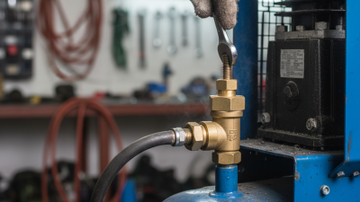
Installation conditions often decide whether a suitable valve works correctly. Mount the valve directly on the protected vessel or approved outlet, with a short, unobstructed inlet path. Discharge piping should direct air away from workers and equipment. It must also tolerate vibration, moisture, and the expected temperature. Never reduce the outlet without confirming the manufacturer’s flow calculations. Small details matter.
The U.S. Department of Energy reports that compressed-air leaks can waste 20% to 30% of compressor output in poorly maintained systems. That figure is not a relief-valve rating, but it shows why system conditions deserve attention. Contamination, pulsation, and frequent cycling can affect valve performance. A common mistake is choosing by thread size alone. I have seen that shortcut create expensive rework. Check the vessel data plate, local code requirements, test records, and installation drawings before purchase. Recheck the assumptions.
Checking compatibility, certifications, and installation conditions
Illustrative pressure-selection examples in bar(g). The set pressure must be verified against the actual MAWP, operating pressure, applicable code, and local regulations.
A relief valve is the compressor’s last barrier against dangerous overpressure. Choose one with a set pressure below the receiver’s maximum allowable working pressure, not merely below the compressor’s normal discharge pressure. ASME Section VIII and the National Board Inspection Code emphasize certified sizing, correct installation, and traceable inspection records. In practice, verify the valve’s capacity, connection size, temperature range, and compatibility with air service. A valve that fits the pipe may still be unsuitable.
Testing must reflect actual operating conditions. Inspectors should check for corrosion, blocked outlets, damaged seals, and evidence of tampering. Never paint, cap, or isolate the discharge path. The U.S. Department of Energy reports that compressed-air leaks can waste 20–30% of compressor output, showing why small losses deserve attention. However, a leaking relief valve is not simply an energy problem; it may indicate contamination, pressure instability, or a failing seat. Keep records. Record the test date, set pressure, result, and technician.
Tips: Use a controlled test procedure and calibrated instruments. Follow the interval required by local rules, the equipment manual, and site risk assessment. API 576 recommends using service history to determine inspection frequency, rather than relying on one universal interval. Replace the valve after a failed test, persistent leakage, severe corrosion, or uncertain service history. A perfect schedule is unrealistic. Review it after repairs, pressure changes, or repeated nuisance lifting. Then ask the harder question: did the valve fail, or did the system create the failure?